I recently acquired a (used, of course) Zoom MRT-3B drum machine, a cute little beatmaker from the early aughties (2003, best I can tell). I noticed after playing with it a few times that it was losing all user content every time I turned it off and on, displaying “Init” on startup. Turns out this is not because it’s Bri’ish, but is short for “initialize” which means, in effect, it’s erasing all user content. Bummer.
It occurred to me that this probably comes down to it storing user settings in battery-backed ram, and said battery was probably extinguished at 21 years of age. So I set about finding and replacing the battery in question. Sadly, I didn’t think to blog this for posterity until all was said and done, so I have no pictures for this tutorial. Nevertheless, hopefully it helps someone restore their machine to full use.
If you build electronics, you know the feeling: you’ve been hunched over the workbench all night, soldering, trimming, testing, squinting. Your hands feel like like they’re covered in flux, your “soldering time” playlist is in its 4th time through, and your forehead has a permanent goggle mark. And then — it’s done!
And you plug it in, light it up, and … nothing happens. It no workee.
Over the last two years, I’ve built well over a hundred guitar pedal circuits, almost all of them on vero board (a.k.a. strip board) and I know the feeling quite well. The majority of my builds, even now, failed the first time I fired them up. So much so that I’ve just come to expect it at this point. However, I’m proud to say that I do not have a bin full of bad builds anywhere in my workshop, because with a bit of troubleshooting and correction, I’ve managed to make them all work in the end. Not because I’m some engineering genius, but because I follow simple procedures and never give up.
Since I’ve seen a lot of people posting online that their vero builds don’t work, I’m posting here my methods for successful building on vero board.
Part 1: Preventive strategies in the pre-build stage
Let’s kick this off with a few things we can do before the build to mitigate the possibilities of errors in our builds.
Verify your layout
If you’re working from a published layout that’s been verified by others, you’re all good here. But if you’ve made your own layout using a program like DIYLC, you’ll want to make sure you got it right before actually building it.
To do this, I put my layout and the schematic up next to each other on the screen. Then starting at some point (say, the audio input or Vcc) I compare what should be connected at that point according to the schematic with what is connected on the vero.
If you kept your component names the same between the schematic and the layout, you can also generate a netlist, which essentially lists all the points at which components connect and which components are connected at that point. This is a lot more fool-proof than working out vero connections visually.
If everything that should be connected at each point is connected, and nothing else, then you should be good to go.
Prep your layout
Half the battle in building on vero is knowing where a component should go and making sure it gets there. There are some things we can do on our layout that will help that to happen.
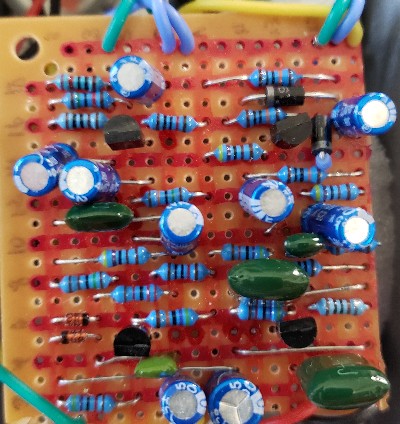
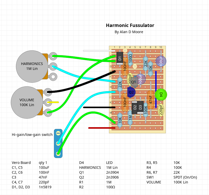
An example of one of my vero layouts. Not exactly consistent with my color code, but you adjust as needed.
If you’ve made your own layout, make sure that the numbers and letters denoting the columns and rows are clearly visible along the edges of the board. I find the default settings for this in DIYLC are a little light for me, so I’ve adjusted them.
If you’re using a layout from somewhere else, like Tagboard Effects (one of my favorite sites), it may or may not have numbers and letters, or have them clearly. I suggest either editing the image to have clear column & row markers, or just printing up the layout and writing them in.
For very large layouts, you might also want to use a highlighter to stripe alternate rows and columns, as it’s easy to get lost in the middle of a large board.
I also very much prefer a layout that displays component values (at least for caps and resistors) over component names (R1, R2, C3, etc). It really doesn’t matter at the build stage if I’m putting in R1 or R17, what matters is if it’s a 10k or a 47k, so having those directly on the components means one less step to get it right.
Prep the board
Once my layout’s ready and I’ve cut a piece of vero to size, it’s time to prep that board. Again, the goal here is primarily to make sure components end up where they’re supposed to be. To that end, I do the following:
Number & letter the board: Using an extra-fine-tip sharpie, I number and letter the columns and rows to match my layout. I typically only do the even columns and rows as it’s less cluttered and more than sufficient.
Stripe the board: Using colored sharpies, I stripe every other row and column of the board on the component (non-coppered) side. If it’s a particularly large build, I may do every tenth row in a different color. If I have any “dead rows” (an extra one on the top or bottom that isn’t part of the layout), I’ll black that one out.
Mark the cuts: Using a paint marker, I mark each dot on the component side where I’m going to do a trace cut. The reason for using a paint marker is that you can create a bubble of paint inside the hole that dries and can be seen from the copper side (I suggest using red, since it’s got the best visibility). Since most layouts display cuts from the component side, marking them on this side means you don’t have to flip the image around. Also, these markings act as reference points to make sure you’re putting components in the right place.
A prepped board. Christmas colors!
Once you’ve done all this, give your ink a bit of time to dry and get ready for the build.
Part 2: Building for success
Fire up the iron, switch on the extraction fan, and turn up the tunes, it’s time to build!
Make clean cuts and test them
The build starts with making our trace cuts. If any of your markings failed to retain their paint bubble, you can touch them up; otherwise, just flip the board and you should be able to make out which holes have a bit of paint in them. If you’re having trouble seeing, put a white sheet of paper behind the board and make sure your lighting is adequate.
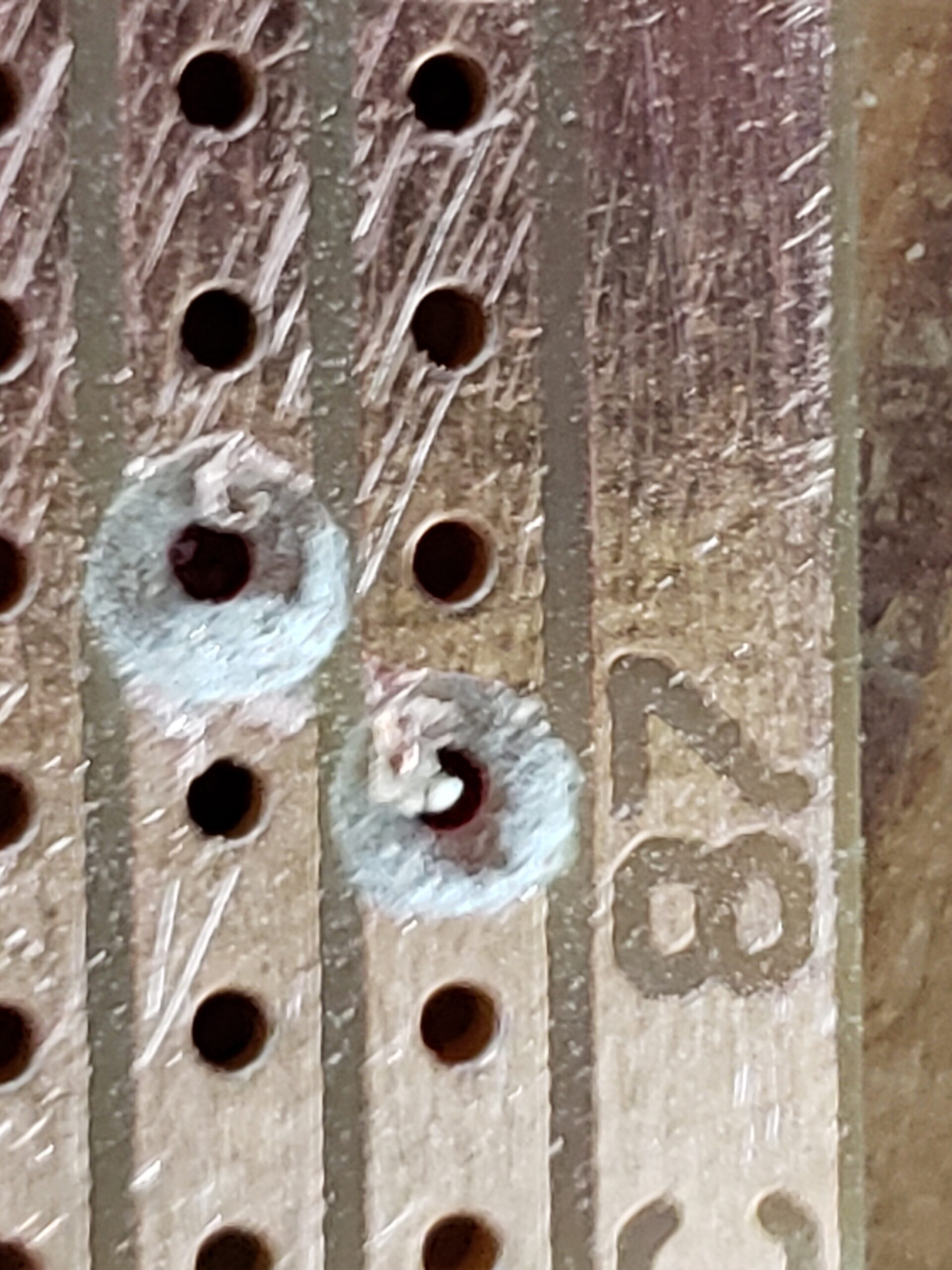
These holes need more work. Note the bit of copper trace in each one.
When I started I used an exact-o knife to carve out each hole, but that’s tedious and tends to leave bits of copper around the edges. Now I use a pin vise with a drill bit just a bit larger than the width of the trace. Put the bit in the hole and give it a few spins. Clean cuts every time.
Once you’ve done all your cuts, give the copper side a light sand. I like using a cheap sanding sponge for this, but any medium-grit sandpaper should work. Inspect your holes to make sure there are no stray tails of copper tracing that could form a bridge. If there are, clean it out with your drill bit.
Finally, before moving on, check your cuts. Get your multi-meter in continuity testing mode and pop the leads on either side of each cut. Make sure they’re all genuine breaks before moving on.
Solder and soldering tools
Before we get into soldering, let’s talk about our solder and tools.
A mistake I made early on was using solder that was too thick. I switched to .6mm solder and it made a world of difference. Thinner solder gives you more control over how much solder you’re using and makes for a much cleaner build. I’m also using 60/40 Tin-Lead solder (specifically this brand, and yes that’s an affiliate link. If I’m going to plug a product, I might as well get something for it, friends).
Regarding lead in solder: I make no claims to be a medical expert, but my understanding from more experienced builders is that the real concern with solder is not the lead (assuming you know how to wash your hands and not eat Cheetos while building), but the fumes. The fumes from any solder are bad to breathe, but the fumes from lead-free are apparently worse. So do your best research, make smart choices, and use a fume extractor.
Now, about your iron. If it doesn’t have a temperature control, sell it on ebay and get one that does. There’s no reason not to at this point, you can get a decent soldering iron with a temperature control for dirt cheap. I upgraded to the relatively pricey Hakko a while back (part of a pedal trade), but was perfectly happy with a generic Chinese brand before that.
I set my iron to 650°F, which seems to me is just past the point where solder melts reasonably fast. I have yet to burn out a component at this temperature, even when soldering ICs directly to the board.
As for tips, it’s a question of preference, but I’ve been happily using my Hakko’s included chisel tip for about half a year now. Spend the money to get quality tips, too; the big 20-pack of random-Chinese-brand tips from amazon will corrode quickly.
A few more random tool suggestions (with more affiliate links, sorry) for solder time before we go on:
solder sucker: I use the Vampire Tools one and it’s worth to extra cost over cheap plastic versions. This is the do-over tool you need for cleaning up messy solder joints.
Helping hands: Not strictly necessary, but useful. I use this six-armed version , and while it’s overkill in most situations it’s quite, well, handy, for keeping track of various bits and bobs during the build. I augment it with slightly larger alligator clips from the craft store as I find the clips most of these things come with to be inadequate. Whatever you get, get one with a big sturdy base. The uber-cheap ones you usually get in beginner soldering kits that look like they could be a cute stop-motion character are ultimately junk. Skip those and get something solid.
Sticky tack: Sometimes this just works better than the helping hands or any of the other fancy tools available to hold your board. Use it to keep the board in place while you solder.
Needle-nose pliers: Useful for pulling resistors tight to the board, I particularly like the bent variety.
Reverse-action tweezers: Leave the eyebrow tweezers in the bathroom, you want the kind that are normally closed. Although I keep both kinds on my workbench, these are the ones I reach for more often. Great for bending leads or extracting a wrong component, etc.
Magnifying head lamp: My vision isn’t great to begin with, and at my age it’s getting harder to get a focus on things as small as circuit components. I don’t want to have my eyeballs anywhere near a soldering iron, so I have a headlamp with magnifying lenses. In particular, I use this one. Works a treat. If you don’t use this (and don’t wear glasses), at least put something solid between your eyes and your soldering (safety goggles, for example).
Alright, tools ready, let’s get to building.
Placing components
This is the part where the mistakes usually happen, so let’s really take our time here friends. Go SLOWLY. Like really slowly. Like octogenarian using Windows 98 slowly.
There are different approaches to populating a board. Some people prefer to put in all the components, bending out leads to keep them in place, then flip and solder.
This method may work OK for PCB, but I don’t like it for vero; for one, I want my components as close to the board as possible. I find bending out the leads doesn’t hold the components that well, and also leads to solder bridges on vero (since you’re bending them out towards adjacent tracks). Also, having a forest of component legs to navigate makes it harder to solder and easy to miss a joint here and there.
My approach is to work my way through the build one to three components at a time, starting with the shortest and working up to the tallest. Rather than suspending the board in mid-air, I lay it flat on the desk or a small piece of scrap wood so the components are pushed up against the board.
This is roughly the order I work in:
Jumper wires
Small glass diodes
Resistors laying flat
Big plastic diodes
Ceramic caps
Chips or chip sockets
LEDs
Box caps
Standing resistors
Poly drop caps
Electrolytic caps
Naturally if you have some oddball component like a vactrol or inductor, you just figure out where it fits in the order of vertical size. The reason for this approach is that when you flip the board, you want the component making contact with the workbench so it’s pushed flush with the board.
Every time you place a component, double-check your placement. I think half my errors on vero are wrong placement. Check the row and column for each lead, and check it in relation to other components or trace cuts on the board. Double — no, TRIPLE — check your polarity on polarized components. An exploding electrolytic cap can ruin your day.
If you have long jumper or component lead runs, especially if you have two in parallel, consider insulating them. I keep the little bits of silicone insulation I take off the ends of wire and slip these over the jumpers or leads when necessary. Super handy and free!
Soldering
Soldering is a skill that takes practice, and doing it well makes a big difference in the robustness of your builds. Fortunately, you can redo your joints (within reason) and take the time to get them right.
I won’t rehash the numerous soldering guides you can find all over the internet, but I’ll just add these tips:
Keep your iron on that solder until the flux bubbles and you see it flow, not just until it melts. It should naturally spread along the copper when it’s flowing.
For vero, be especially vigilant for solder bridges. If you have big blobs of solder creating bridges, suck it up and do it over. For smaller bridges I find it helpful to just run a hot, clean iron between the rows.
As mentioned before, I try to avoid bending out component legs when using vero. I find that keeping the legs straight up (perpendicular to the board) results in the cleanest joints.
If your soldering game is sloppy despite your best efforts, you may need to consider better tools.
As with placement, take it slowly and get it right. And oh yeah, use a fume extractor.
Let’s talk wire
Once all the components are the board, you’re going to add the wire for the off-board stuff. I usually wire in all my pots and switches and just have bare leads going out for power and input/output. I hook those leads to a tester box or breadboard for tests when the build is done.
Wire preferences vary, but I like to use 24 AWG stranded wire with silicone rubber insulation, specifically this brand (affiliate link again). While solid core is easier to get through the holes, its rigidity is a liability over time. 24 AWG is just the right size to poke through a vero hole when you give it a twist or two. You do need to be vigilant for a stray strand, especially if you have wires connected in adjacent rows. I recommend giving it a good twist and a very light tinning.
The silicone insulation, by the way, is great. Soft enough to strip with your thumbnail, doesn’t melt under the heat of the iron, durable and flexible. As mentioned previously, I save the little bits I pull off (a.k.a. forbidden sprinkles) for insulating component leads and jumpers when necessary.
I also take advantage of having wires in different colors to make it clearer which wire is which. I have my own personal color code, which you are free to use or ignore, that goes like this:
Black: Any connection to ground.
White: Any connection to the supply voltage
Red: Signal input
Yellow: Signal output, or pin 1 of a potentiometer or switch
Blue: Pin 2 of a potentiometer or switch
Green: Pin 3 of a potentiometer or switch
Sometimes I have to mix these up depending on my wire supply or if sticking to it would be confusing, but staying relatively close to a consistent color code (on my layouts as well) helps me not make silly mistakes with wiring.
Part 3: The Due Diligence
After all my components are in and the wires are on, there’s a final procedure I call “The Due Diligence”. These steps eliminate a lot of common very errors, so don’t leave them out.
Visual inspection: Check the board. Any component leads not connected? Anything sticking up too high? Any unintended connections on the component side? Any visible bridges on the solder side? Any components left out (happens a lot…)?
Trim the leads: You probably trimmed while soldering, but take time to really trim back anything that’s sticking out. The more lead you have hanging out the more chance it can ground against the enclosure or come into contact with something it shouldn’t. Trim it back to the solder, especially wires which can get a bit frayed. If you accidentally trim into the solder, get your iron and reflow it in case you’ve introduced a crack.
Check the gaps: Take an exact-o knife and score lightly in the gaps between rows on the copper side. If you run into resistance, it could be a solder bridge. Knock out any resistance, or if it’s particularly heavy run your soldering iron (nice and clean tip) between the rows too.
Clean the copper: After removing the bridges, clean the copper. I use isopropyl alcohol and one of those cheap toothbrushes the dentist always gives me. Afterwards brush off any debris with a dry paintbrush. This will remove some of the flux too, which is good to remove.
Once you’ve done this, do another visual inspection and clean up anything you missed. If I’m checking for bridges as a debugging procedure, I may use a phone camera at high zoom to look for tiny bridges too small to see.
Part 4: Debugging
You did ALL of the above, plugged it in for testing and… it’s not working. Now what? No, don’t pop it into the dud bin just yet. We can fix this!
Triple/Quadruple/Quintuple check
Before we get into debugging proper, redo the due diligence. I’ve had misplaced components make it through two or three visual inspections. We humans are just not that good at spotting these things. Even if you feel certain, don’t rule out a misplaced component.
Triage
Ultimately, debugging anything (software, electronics, making pickles, etc) is the same basic process:
Start with an assertion — that is, a fact that should be true based on the design.
Devise and execute a test to see if the assertion is true of your implementation.
When a test fails, considerthe reasons that might lead to the discrepancy.
If it’s not obvious, come up with more assertions and test in the surrounding area.
As you find more discrepancies and agreements between your design and implementation, reason towards a cause of failure that explains them.
How do we apply this to a circuit build? To begin with, it’s incredibly helpful to have a schematic. Often with vero you may be building from a layout and not have had an actual schematic; now it’s time to acquire one. Make sure that you’re using the same schematic that was used to create the layout, including any modifications. If you can find a schematic or other reference that includes expected voltage measurements at different points in a circuit (particularly on the pins of transistors and ICs), this is also incredibly helpful. As a last resort, you can always just reverse engineer a schematic from the layout.
Also, take note of exactly how the circuit is malfunctioning (or not functioning) so you can be somewhat smart about your debugging. Is it completely dead? Probably something in the power circuit. Is it lighting up but no output? Probably an issue with the signal path.
If you’re doing audio circuits like the guitar pedals I build, an audio probe is a vital tool here. It doesn’t have to be anything you buy, just a lead going to a largish (100nF+ non-polarized) capacitor going to an amp (with the amp’s ground connected to the circuit’s ground).
To begin probing audio, first identify the signal path on the schematic. This is the path that goes from audio in to audio out, and there may be more than one. In theory, there should be an audio signal at any point along that path (usually). With some audio hitting the input (a cheap mp3 player or looper pedal is useful here), start at the input and touch the probe after each component along the signal path. Note the point where it fails or does something unexpected (gets distorted when it shouldn’t, gets notably quieter, etc).
Assertions to test
Assuming you’ve got a schematic and you’ve already traced the audio path (if applicable), here are some other things you can check:
Grounding: Set the multi-meter to continuity mode. Clip one side to ground and touch every point that is supposed to be connected to ground. For audio circuits, you can also test each point in the signal path, none of which should be grounded (otherwise your signal would just shunt to ground).
Voltages: Check and note the voltages at the supply input, and on each pin of a transistor or IC. Even if you don’t have a schematic listing expected voltages, there are some you can just reason out. For example, the Vcc pin on an IC should have something close to the supply voltage, the ground pin should have 0 volts. Or, if you’re working on a single-supply audio circuit, your op-amp and transistor ins and outs should have a bias voltage. The more you understand about circuit design, the more you can reason out here.
Continuity: Don’t take continuity for granted. With the circuit un-powered, check continuity between the lead coming out of a component and the leads going in to any component it’s supposed to connect to (I once found a bug that took three days to find this way; a socket leg had folded under and there was no connection to the board).
Once you’ve gone through all this, you should have a pretty good idea of where the problem starts, even if you don’t know exactly what the problem is. A failed continuity is pretty straightforward to correct, but a voltage that is off is more subtle problem to resolve.
Identifying the problem component
If you see a problem starting after a component, you might be tempted to immediately conclude you have a bad component. Unless you’re buying your components on eBay from low-rep sellers or soldering with a blowtorch, it’s probably not the component. Just because a problem (like sudden loss of audio) starts after a particular component, it doesn’t always mean that component is bad. For example, you may have a coupling capacitor going into an op-amp that’s mistakenly biased to the full supply voltage. The signal will stop after the cap because of the bad biasing on the op-amp, and be present on the other side of the cap because it blocks the DC biasing voltage. The cap is fine, the problem is with some component involved in biasing the op-amp.
More than likely you have a wrong component or wrong connection somewhere in the vicinity of the problem area. Check all these things again and pay close attention to detail, because if it’s gotten past you to this point it’s something subtle (was that supposed to be 56k or 56 ohms?).
Of course bad components exist and damage during building does happen. Components I might be tempted to suspect are semiconductors (LEDs, diodes, transistors, ICs, etc), electrolytic caps, potentiometers, or switches. Most other common components (resistors, poly caps, etc.) are pretty resilient. If you suspect a component is bad, take it out of the circuit and test it. Sometimes you can test in-circuit, but it’s better to eliminate any variables.
Still not working?
When you do find and fix a bug, it’s tempting to think to yourself, “I’ve fixed the bug!”. But be careful, my friend; there can be more than one. And there often is, especially in very complex builds. I’ve had as many as five or six errors in a large vero build (including accidentally putting in the wrong value for 14 resistors).
Also, don’t assume your test rig works. Verify everything. For my pedal circuit test rig, I have a bypass switch so I can quickly make sure the guitar, cables and amp are working before checking the circuit (I was scratching my head over a buzzy build one day only to find the ground wire in my test guitar had come loose).
Conclusion
Hopefully this guide has got your circuit going and spared from the busted box. Did I forget anything though? Feel free to drop a comment on your techniques for successful vero builds. Thanks for reading!
Joining a GNU/Linux machine to a Microsoft Active Directory has been possible for years, but it’s always been a bit of a science project that involved touching half-a-dozen obscure config files and usually resulted in me getting completely locked out of the machine. Various commercial packages such as Likewise and Centrify aimed to smooth out the process, but they weren’t universally accessible across distros, and often produced inconsistent results.
After upgrading a system to Debian 8, I noticed a new option for joining the domain, courtesy of the folks at RedHat: realmd. Realmd puports to make joining an Active Directory domain dead simple. How does it do?
The previous articles in this series helped you set up a Linux-based system for a child, and explored some of the great educational and kid-friendly software available. I’ve based this on almost eight years of experience in setting up GNU/Linux on computers for my own kids, and for their friends. So, based on that experience, what things do I wish the Free software community could come up with to make Linux a better experience for kids (and their parents!)?
By now you’ve got that old computer purring along like a panther with your new favorite distribution of Linux, loaded to the brim with educational software, ready to propel your child to the heights of intellectual stimulation. But before we launch this starship, let’s take a bit to make sure the safety equipment is in order and reign in some potential problems.
The last article in this series described some of the more general realities of running Linux on a child’s computer. Now that I’ve (surely) convinced you to go ahead an put GNU/Linux on your child’s computer, it’s time to get down to nuts and bolts: which distribution, and what software?
One of the common suggested uses for old computers is to install GNU/Linux on it and give it to your kids. I have five children, ranging in age from pre-teen to infant, and all but the youngest (naturally) regularly enjoy the use of computers running some variant of GNU/Linux. We’ve been using it at home since about 2005, and over the last eight years I’ve gained a reasonable amount of experience setting up Linux on computers for my children or their friends. This series of articles will cover some of my insights on setting up a Linux computer for kids.
So often with Linux distributions, the choice is between running a bleeding-edge system, or sticking with stable (and sometimes stale) software. Most of us settle in to a distro that balances both to our liking, but there are times when you just have to have a little newer version of a package than the default repositories offer. While it’s great to find a backport repo or PPA that offers newer stuff, sometimes that’s not possible.
So for times like that, I’m going to describe a method by which Debian or Ubuntu users can backport their own software using handy little tool called “apt-src”.
Ubuntu 12.04 is nearly upon us, and probably will be by the time anyone bothers to read this post. With all the excitement and general hubbub around it, I imagine it will result in a lot of people unfamiliar with Ubuntu or GNU/Linux trying it out for the first (or first-in-a-long-) time.
There is a lot of good general advice out there, but I’m going to give a few specific tips of my own for folks trying it out:
Following on the heels of my google search hotkey in awesome, I decided to tackle expanding the functionality of the run prompt. Awesome’s run prompt, by default, is basically a command-launcher; it chokes on any input that doesn’t represent an executable file.
I wanted it to behave more like the run prompt in other desktops, so that typing in a URL would open the URL in an appropriate application.
With help from Alexander Yakushev on the awesome mailing list, I managed to figure it out….
My latest book, Mastering GUI Programming with Python, is a great choice for intermediate Python programmers who want to explore the powerful features of PyQt5. It can be ordered now in print or e-Book from Packt Publications or Amazon.
My first book, Python programming with Tkinter, now in its second edition, is aimed at beginning programmers who want to start creating GUI applications using Python's built-in Tkinter toolkit. It can be ordered now in print or e-Book formats from Amazon