At the beginning of the new millennium, a DIY pedal builder known as Hemmo published a circuit design he dubbed the Bazz Fuss. As the name implies, the circuit was designed for use with Bass, and tends to have a fat low-end and somewhat synthy distortion. Many would agree it sounds great with guitar as well.
The spartan design, consisting of only 5 components — 2 capacitors, a transistor, a resistor, and a diode — delivers a surprisingly powerful and unique fuzz sound. As such, it’s become a go-to first build for aspiring DIY pedal builders and tinkerers. Not only is it an easy first build, but it also lends itself well to experimentation with different components. And as we’ll see later on, its concept can be applied to other circuits to create novel fuzz sounds from old designs.
This article is a dump of my knowledge obtained from a few years of reading about, tinkering with, and designing different fuzzes from the bazz fuss.
1. The vanilla Bazz Fuss
The basic circuit topology of the bazz fuss looks like this:
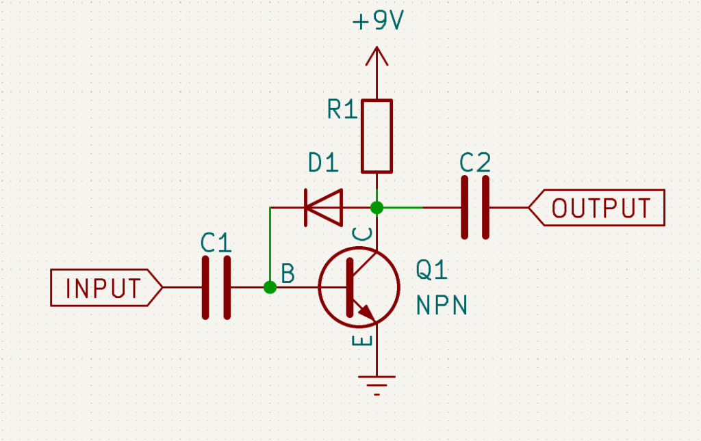
Hemmo’s original schematic gave the following component values:
| Component | Value |
|---|---|
| C1 | 4.7µF |
| C2 | 0.1µF |
| D1 | 1n4148 |
| Q1 | 2n3904 |
| R1 | 100k |
These are a reasonable set of values to begin with, and as of this writing they’re all common components readily available for less than the price of a pack of gum. Even so, many beginners get tripped up because they are working with a different diode or transistor. So let’s talk about each of these components, what they do, and how different choices will affect the signal.
1.1. The coupling capacitors
As with any single-supply gain stage, coupling capacitors C1 and C2 are essential both to block any possible DC voltage on the input or output, and to “contain” the bias voltage present at the base and collector of the transistor. Of course, both will cut some low frequency content as well. We can adjust the amount of low cut before and after the fuzz by altering the values of these capacitors:
- Making C1 smaller will cut more bass from the signal before the fuzz. That also attenuates the input signal, so it will be less fuzzy overall.
- Making C2 smaller will cut more bass after the fuzz, meaning you’ll get the full fuzz effect, but with less bass.
The exact frequency affected by C1 and C2 is a tad complex, as it interacts with the impedance of the transistor stage, which itself will vary depending on your choice of Q1, D1, and R1. What’s more, it’s different for the upwards and downwards voltage swing of the circuit. The usual approach for those wanting to tighten up bass response is to adjust these capacitors by ear.
1.2. The Diode
Virtually any diode will work for a bazz fuss, but they won’t all produce the same results. The most critical value to consider in diode selection is its forward voltage, or Vf. This value will have a significant impact on the output volume of your circuit as well as the amount of fuzz. The suggested 1n4148 is a common silicon diode with a Vf in the 600 to 700 mV range, which provides significant fuzzing and an output a good bit louder than a typical passive guitar signal. LEDs are another popular choice, with Vf values in the 2-3V range depending on color. These give an exceptionally loud output and slightly more headroom (or less fuzz). Going the other way, germanium or Schottkey diodes give extreme amounts of fuzz but also lower output (potentially quieter than the bypassed signal) and require a higher R1 value (more on that in a bit).
Beyond the Vf value, different diodes will exhibit minor differences in their I-V curves and capacitance. The I-V curve describes the rise in conductance as the voltage across the diode approaches Vf, and will have some impact on the dynamic response of the fuzz. The diode’s capacitance may cut high end if it’s large enough, though this is likely to be subtle with most diodes. Zener diodes, in particular, tend to have a large capacitance that impact the tone of the fuzz. While either effect may be negligible, don’t hesitate to try various diodes in your circuit even if they have similar Vf.
1.3. The transistor
The transistor is the heart of the fuzz, and luckily the bazz fuss isn’t picky about which one you use. Almost any NPN BJT will work fine; the original circuit’s 2n3904 was almost certainly specified because of its ready availability and cheapness, rather than any special quality of function. In fact, many subsequent schematics for the fuzz specify a either a Darlington transistor or two standard transistors in a Darlington pair arrangement. This gives us a much higher current gain (hFE) value, which both provides a louder output signal and makes it easier to bias the circuit for a smooth cleanup.
Going the other way, low hFE transistors (those with a value under 100 ) don’t work so well for a bazz fuss, both because the output volume is too low and because it’s harder to find a good R1 value that will bias the circuit correctly. For that reason, it’s my suspicion (though I haven’t tested this empirically) that Germanium transistors, mojo notwithstanding, would not make for a good bazz fuss (since they tend to have low hFE). For best results, stick with silicon transistors in a Darlington pair.
1.4. The resistor
The resistor is the unsung hero and misunderstood genius of the bazz fuss, and often the part that sabotages a beginner build. Its job is to limit the current available to the diode which is madly trying to keep the transistor base at one Vf value below the collector. Depending on its value, you can obtain either a spitty, gated, “velcro rip” fuzz or a smooth breakup that cleans up nicely when you roll back your guitar volume.
The 100k specified for the original design will minimally work for its diode and transistor combination, but for best results you should really discover this value with some experimentation. The ideal R1 value will depend on the forward voltage of the diode and the current gain of the transistor. It could be as low as a few kilo-ohms or as much as a mega-ohm; in general, you’ll find a high-Vf diode and high-hFE transistor will allow you to have a smaller resistor, as well as giving you more latitude for finding a good value.
The ideal way to find this ideal R1 value and obtain a smooth cleanup on the bazz fuss is:
- Breadboard the circuit with your chosen transistor and diode.
- Put a 1M pot as a variable voltage in series with a 1k resistor as your R1 value (the 1k is to prevent accidentally frying the semiconductor parts with too much current). Set the pot to 0.
- Plug in your guitar and turn the volume down quite low (About twenty percent or so).
- Strum while turning up the 1M pot. When the sound comes through without any brokenness or spittiness, you’ve found the spot. Remove the pot and measure the resistance between the two lugs you connected to the circuit.
Of course, this assumes you want a smooth cleanup; If a spitty, gated fuzz is desirable, you can leave the guitar volume up and just tweak the pot until you find the sound you’re looking for. If you want to have some flexibility, putting a trimpot here in your final circuit isn’t a bad idea.
Note that very high R1 values can start to dull the tone and reduce both the fuzz and output volume, so it’s not the best idea to just use an arbitrarily high resistor.
1.5. How does the circuit actually work?
All this talk of components is fine, but how does this circuit actually produce a fuzz sound? A great explanation was provided by Andy L (a.k.a. Fancy Lime)on the DIYStomboxes forum many years ago, which I’ll try to summarize the main points here:
- At rest, the diode keeps the DC voltage at the base one diode drop (Vf) under the voltage at the collector.
- When the base sees an input signal that goes below ground, more current tries to flow through the diode to counteract the swing and keep the base to one Vf below the collector.
- The Resistor, however, impedes the current flow so that this can’t happen perfectly. The result is a lot of distortion from the diode clipping.
- When the base signal swings back up above ground, the diode is reverse-biased and cannot provide negative feedback, so the transistor’s amplification maximizes. The result is distortion from transistor saturation.
The end result is an asymmetric clipping caused by the diode on one side and the transistor on the other. You can also see here how important the right resistor value is, because it controls the diode’s ability to bias the base.
2. Modifications to the Bazz Fuss
While the bazz fuss is a solid fuzz circuit on its own, there are a variety of ways we can refine and improve on the idea to make a more serviceable fuzz. This section is going to examine some simple ways to modify the vanilla circuit.
2.1. Small pragmatic fixes
To begin with, there are certain very simple “quality of life” fixes that should be part of any bazz fuss build.
2.1.1. Volume pot
Given that the output of a bazz fuss is likely to be louder (sometimes MUCH louder) than the raw guitar signal, a volume pot is a must-have addition to any build. A simple voltage-divider-to-ground pot is sufficient here, as shown here:
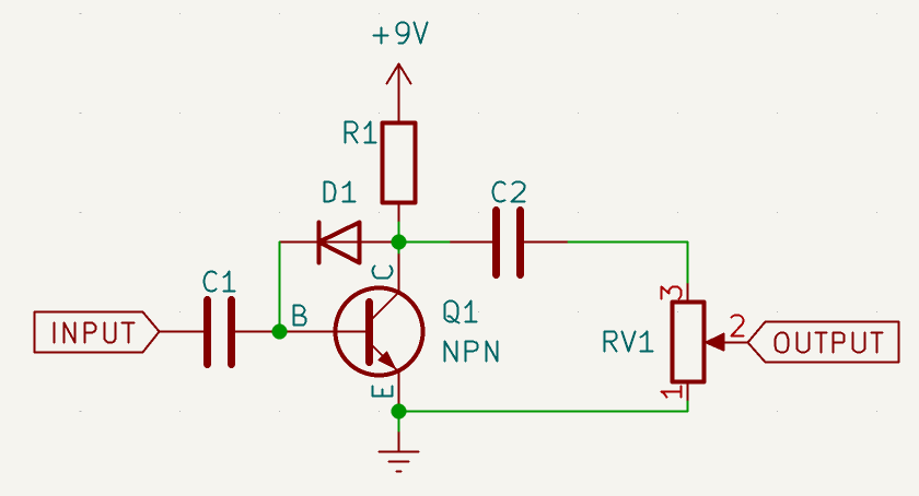
The exact value of the pot is not critical here, though lower is preferable since we want our output impedance to be low. Keep in mind, however, that the pot will form a high-pass filter with the output capacitor. Using the original 100nF output capacitor, we can safely use a 100k pot here and the resulting bass cut will be around 15Hz, below the range of human hearing. Should you need to go smaller with the volume pot, a larger output capacitor might be in order if you wish to retain the original bass response.
2.1.2. Miller capacitor
Transistors, particularly older ones, exhibit a certain amount of capacitance between the collector and base, known as their Miller capacitance. This capacitance results in a rolloff of high-end frequencies. Of course, with a fuzz, high-end rolloff is not always a bad thing, and in some cases might prove desirable. Most “modern” silicon transistors have a very low Miller capacitance (often just a few pF), so any filtering is outside the range of human hearing. This can result in a sound that is overly bright, has a whistly noise, or is prone to oscillations.
To correct this, we can add our own Miller capacitance in the form of a small capacitor from the collector to the base. Even if your bazz fuss is not overly bright, a small capacitor like this can help remove noise or radio-frequency interference. The exact value depends on several other factors, but generally something in the range of 20 to 30 pF is a good place to start if you simply wish to remove RFI. If you want to start cutting into the high end output, start with 100pF and adjust up or down to find a good compromise between darkening the sound and removing any objectionable noise.
2.1.3. Current limiting resistance at the input
If RFI is a problem and the Miller capacitor doesn’t solve it, another helpful technique is to put a current-limiting resistor at the input, just before C1. While it will reduce the input volume (and thus the level of fuzz), I nevertheless recommend it for any circuit you plan to use in live settings. A value of 1k to 22k is typically sufficient, so try a few values and see which does the job without compromising your fuzz tone (higher values will of course reduce the input volume and thus the fuzz).
2.1.4. Power filtering and polarity protection
Any circuit designed during the “battery age” will naturally need a little bit more treatment to get it ready for use with a DC power supply. Most of these supplies are fraught with noise and ripple, and the lack of polarity standardization means an innocent mistake can fry a pedal.
My basic setup involves a Schottkey diode in series, followed by a small resistance, then a large capacitor to ground, like so:
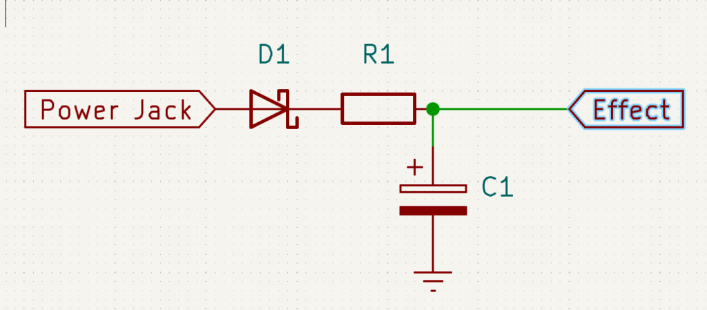
The Schottkey is used because it has a low Vf, so doesn’t steal much power from our supply. You can substitute this with a standard silicon diode in a pinch, and though it will drop your supply voltage more, you’re unlikely to notice a difference. Typical values for the resistor would be around 100 ohms, and 220 µF for the capacitor. If you find this is inadequate for the power supply you’re using, you can increase either of those. Be aware that you will lose some voltage to the resistor as well, but the bazz fuss will operate fine at 8 or 7 volts, perhaps even less. The loss is well worth it to remove power supply noise.
PROTIP: Test your builds using a cheap, nasty wall wart supply. If it sounds good on that, it’ll sound good on a fancy iso-brick. The reverse isn’t necessarily true. As a bonus, if you short something and blow up the supply, you’re only out a few bucks.
2.2. Fancier modifications
Moving on from basic pragmatic concerns, let’s look at some ways we can add versatility and robustness to this simple, but rather limited fuzz.
2.2.1. Gain pot
Hemmo’s original schematic featured a voltage-divider-to-ground input pot as a gain control. While this works with a properly-biased fuzz, it always seems to me a bit redundant with the guitar’s volume pot, especially given that it’s recommended to put the BF first in the chain.
We can create a somewhat more sophisticated gain control by borrowing a page from the Fuzz Face’s book, like so:
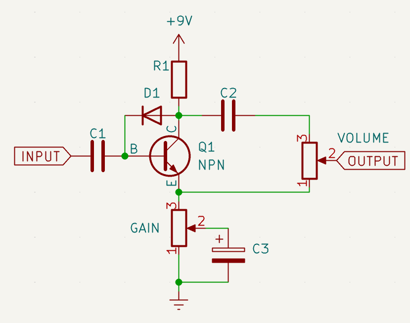
The principle of this knob is simple: The DC current from the emitter to ground stays stable, so the biasing of Q1 doesn’t change. The capacitor, however, passes AC signals to ground. The closer the capacitor’s anode is to the emitter, the lower the AC impedance is to ground on the emitter, and the transistor’s gain goes higher for the AC part of the signal.
Some experimentation may be required to find good values for the pot and the capacitor. The pot needs to be large enough that the signal is fairly clean and roughly “unity gain” when the cap is shorted out of the circuit (that is, when the gain is at minimum). Typical values here will be 1k to 10k.
The capacitor needs to be large enough to pass the full audio range to ground. A typical value here is 22µF (borrowed from the Fuzz Face), though a smaller cap may suffice. A much smaller cap (less than 1µF, for example) will prevent low frequencies from being fuzzed, and may be interesting to experiment with if you want a tighter fuzz sound.
A slightly simpler gain control was proposed by Tim Escobedo (FolkUrban) in his take on the Bazz Fuss, which consists of just a 10k variable resistance between the emitter and ground. His version also used a Darlington transistor, 3 silicon diodes in series for D1, and 22k for R1. Runoffgroove suggests a value of 1k in the same arrangement, but with a smaller D1 and R1.
2.2.2. Pickup simulator
Both Escobedo and Runoffgroove have suggested a “pickup simulator” for recovering the sound of a first-in-chain fuzz pedal when you need to put a buffer or other active electronics before the bazz fuss. This consists of a simple inductor in series with the pedal’s input, usually in the form of one side of a small transformer.
In theory this should just roll off some high end and lower the impedance of the pedal, just as putting the pedal in direct connection with a passive pickup will load the pickup and cause high-end rolloff. While I’ve only minimally tested this idea, I’m not entirely sold on it as effective or even necessary to a good sounding fuzz. As noted earlier, a too-bright response can easily be mollified with a Miller capacitance.
A more thorough pickup simulator circuit is detailed by Jack Orman (a.k.a. AMZ) in this article, but I invite the reader to determine empirically how much difference it really makes.
2.2.3. Headroom control
The headroom, or “Leak” control, is something I discovered through experimentation. It consists of a variable resistance (1M usually) between the Q1 collector and D1. Such a resistance increases the amount of gain before clipping, and has the audible effect of adding clean sound to the fuzzed output. It also greatly increases the volume of the output, so the addition of a volume control is a must here (as if it wasn’t already!). This control makes an excellent addition to a fuzz aimed at bass players as an alternative to a clean blend (which usually requires additional buffering or phase inversion stages).
The basic schematic looks like this:
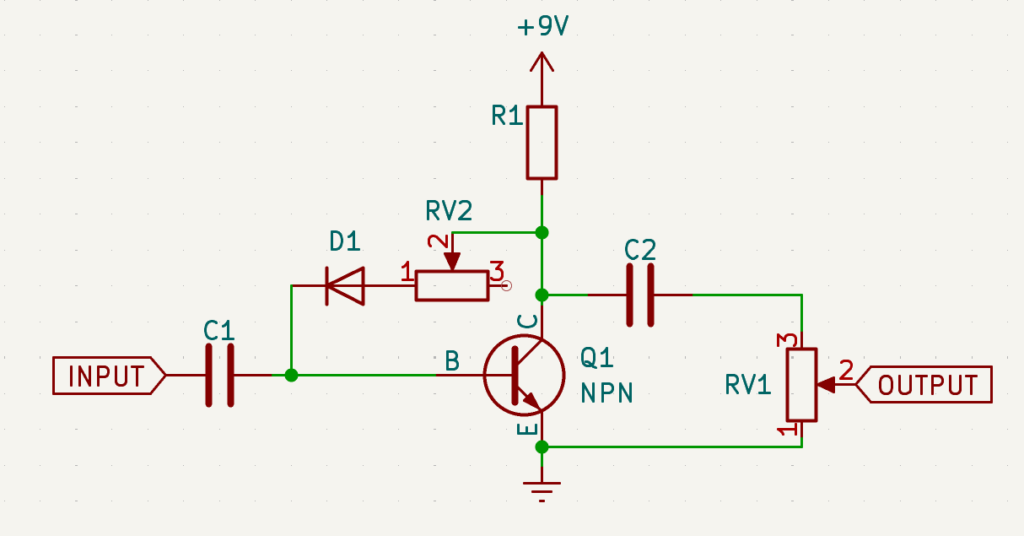
Of course, a fixed resistor or trimpot works here too if you wish to hardwire a certain amount of headroom.
2.2.4. Diode gate
If you want to remove noise from your circuit and don’t mind sacrificing a decent cleanup, one way is to mis-bias the fuzz so that low-volume sounds are just cut off. An alternative method is to introduce a simple diode gate consisting of reverse-parallel diodes in series with the audio path, like this:
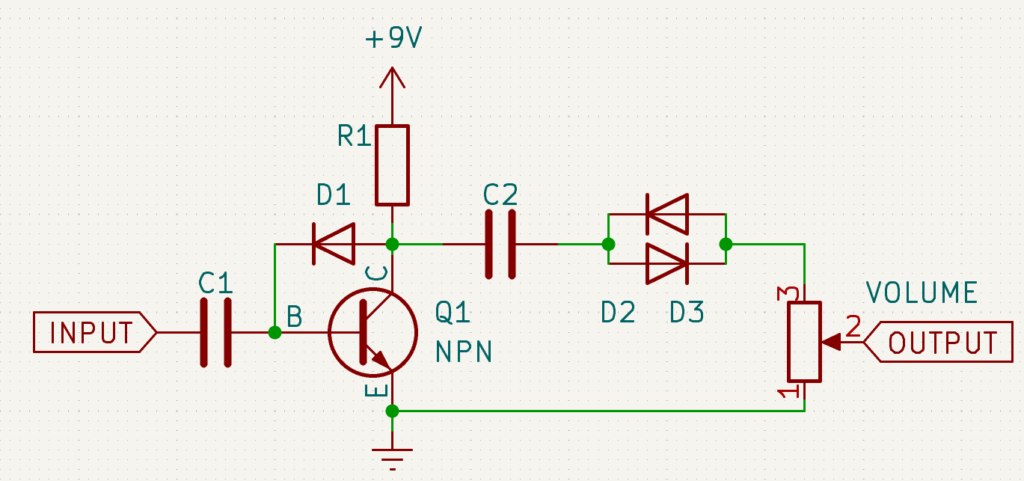
The idea here is that low-level sounds like noise or hum won’t put the signal over the Vf of the diodes, so no signal will pass. The downside is that you get crossover distortion, which is either a good or bad thing depending on what you want from your fuzz. High gain sounds will get some additional brightness and fuzz, but low-gain sounds will be sickly and splatty.
Putting a variable resistance in parallel with the diodes gives you a gate control, like so:
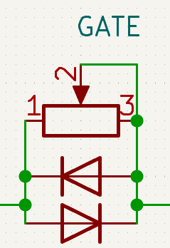
When the resistance is at max, the signal will prefer to go through the diodes and be heavily gated. As the resistance approaches zero, the diodes will be shunted and the signal will not be gated. Choose a pot value that sounds sufficiently gated when at max resistance. I often use 1M, but something smaller may suffice.
This gate can be placed before or after the fuzz, provided that the peak-to-peak voltage of the input signal is higher than the combined Vf of the diodes. For passive guitar pickups, even a pair of Schottkey diodes might be too big a hurdle, so it’s best to put it after. Generally it’s best to have the Vf of these diodes smaller than that of D1.
This addition is of great value when using the bazz fuss in series with other gain stages, especially additional fusses (more on that later).
2.2.5. Additional hard clipping
While the bazz fuss is already quite gainy and hard-clipped, it never hurts to experiment with an additional clipping network at the end of the circuit. I’ve found this to be most effective when paired with a high-headroom fuzz (such as one employing an LED or a headroom control), and in particular when the hard clippers are of a lower Vf than D1. This can also be effective to bring the output of an overly loud fuzz to something more manageable.
If you find a combination that gives a sufficiently different fuzz tone than the fuzz without the clippers, putting it on a switch is a great way to make your fuzz more versatile with only a few components. Alternately, a variable resistance place in series with the clipping network can function nicely as a “saturation” or “compression” control, as shown here:
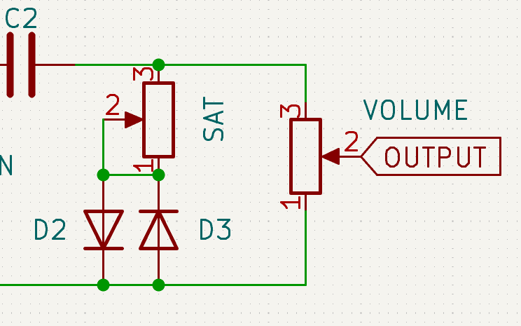
Experimentation with symmetric and asymmetric clipping networks in this way can yield very interesting results.
2.2.6. Tone controls
As with any drive, distortion, or fuzz, the bazz fuss generates a great deal of full-spectrum sound which you can shape with a tone control. When selecting a tone control, volume loss is one of the most important aspects to consider. Any passive tone circuit is going to cost you in output volume, some more than others. Fortunately, the bazz fuss has a potential for extremely loud output levels, so assuming you’ve maximized this with your diode and transistor selection, you have the option to use about any tone stack you wish.
In keeping with the bazz fuss’s spirit of simplicity and low parts-count, a good beginning suggestion is Mark Hammers “stupidly wonderful tone control”. This can be done with 1 potentiometer and 1 capacitor, like so:
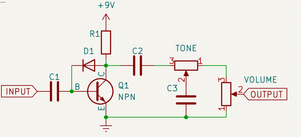
In this circuit, as the wiper is moved closer to pin 1, there is more resistance before the capacitor to ground, lowering the cutoff of the resulting filter. The advantage of this tone control is that the overall impedance never changes, making it less interactive with the volume control compared to other designs (such as the Rat tone control, for example).
To choose components for this control, start with a capacitor that won’t roll off too much high end when connected directly from C2’s output to ground. The exact value here will depend on the other components in your build, but something in the order of 1nF to 10nF is a good starting point. Once you’ve determined that, choose a pot that gives you a good sweep from wide open to muffled. Something in the 10k to 50k zone is probably good there.
Another quite popular option is the Big Muff Pi tone control, which can go from big and boomy to sizzly and thin and features a characteristic mid-scoop that pairs nicely with high-gain sounds. It’s only downside is its massive cost in output volume, so I only recommend it if you’ve designed a very loud fuzz.
3. Even more fun with the Bazz Fuss idea
So far we’ve focused on tweaking a single basic bazz fuss circuit, but let’s take it a little further and see where the concept can take us in the context of a larger circuit.
3.1. Chaining Bazz Fusses
What’s better than a bazz fuss? Two bazz fusses! Runoffgroove’s bazz fuss article suggested early on the idea of chaining two bazz fuss circuits together, which he dubbed the “buzz box” (not to be confused with the DOD pedal). As you might guess, this build results in fantastic amounts of gain and fuzz for those in search of an ultra-high-gain experience. One need not stop at 2 either; I have personally built circuits chaining as many as four bazz fuss stages together, though my feeling is that anything past three has diminishing returns.
Apart from just getting massive amounts of gain, chaining bazz fuss stages, when combined with techniques discussed above, gives us a lot of potential for exploring different combinations of fuzz stage arrangements. For instance, we might chain a choppy mis-biased stage into a smoothly biased stage, or vice-versa. We might chain a stage with a high-Vf diode into one with a low-Vf diode (in my experience, you end up with some interesting sub-octave artifacts in this arrangement), or a muddy, filtered stage into a bright stage.
We can also explore the space between fuzz stages; a volume control, tone control, or diode gate sandwiched between two bazz fuss stages can all yield interesting or useful results.
Of course, chaining multiple fuzz stages will tend to lead to noise and oscillation, but these can be mitigated with careful addition of miller capacitors and diode gates, or by mis-biasing early stages. The possibilities abound!
3.2. Bazz-fussifying other circuits
Reduced to simplest terms, the driving idea of the Bazz Fuss is a diode-biased transistor gain stage. If we think about it this way, we begin to see that we can “bazz-fussify” other transistor-based gain circuits by replacing biasing transistors with diodes and adjusting the collector resistance accordingly. Alternately, we can just replace clipping stages in the circuit outright with a Bazz Fuss, as Runoffgroove did in his whisker biscuit.
To give you an idea of the process here, I’ll detail a couple examples from my own notebook: the Bazzrite Fussrite and the Harmonic Fussulator. More examples from actual builds I’ve done will be shown at the end as well.
3.2.1. Bazzrite Fussrite
The Mosrite Fuzzrite is a classic fuzz with a very simple design: two transistor gain stages are chained together, with a potentiometer fading between the output of stage one and the output of stage two. At the low end of the blend we get a single stage of saturation with relatively low distortion, while the upper end gives us a doubly-saturated high-gain sound.
The original schematic can be seen here:
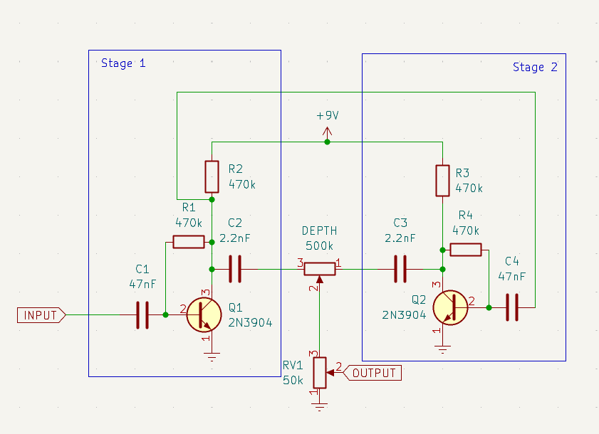
It’s a simple design, and one that can be readily adapted to any two gain stages we might choose – including, of course, the Bazz Fuss. In fact, it’s as simple as swapping R1 and R4 with the diode of our choice, like so:
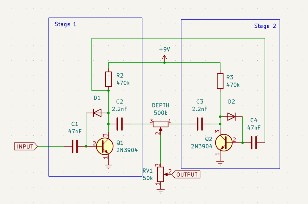
In a way, this is just a variation on the chained fuzz stages discussed in the last section, the difference being that we can fade between the output of one or both stages. As such, you’ll likely find the output of the second stage is a bit too fizzy and some of the measures we’ve previously discussed may need to be employed to tame it. And also as with the chained bazz fuss stages, this circuit is open to some creative opportunities: we can vary the gain, tone, and biasing of each stage to create even more contrast between the blended stages. An example of a circuit based on this idea (“Lobo, King of Currumpaw”) can be found below.
3.2.2. Harmonic Fussulator
The Interfax Harmonic Percolator is one of those classic fuzzes whose most minute details have been pored over and debated by the DIY community for decades, trying to recreate its original legendary sound. But never mind that, it’s also a great circuit topology to experiment with and abuse for science. Rather than starting with a traditional percolator circuit, we’ll start with the “Harmonic Jerkulator” version by Tim Escobedo, which is tweaked to work well with modern commodity transistors. The schematic is shown here:
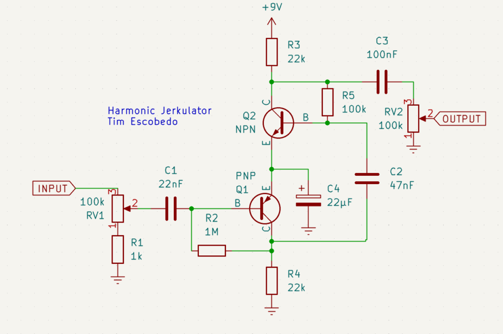
The topology may look a bit confusing, but basically this is a two-stage fuzz, with stage one being a PNP and the second an NPN. The two transistors are arranged interestingly so that the first stage is DC biased by the second one, but from the audio point of view it’s really just a two-stage fuzz. To “bazz-fussify” this circuit, we need to identify the feedback resistors. For Q2 that would be R5 and for Q1 it’s R2. (If you’ve not worked with PNP transistors before, you may be a little confused as to why the feedback resistor is on the ground side rather than the power. That’s because the PNP operates in reverse of an NPN, and current flows from the emitter to the collector.)
Replacing those resistors with diodes, we get something like this:
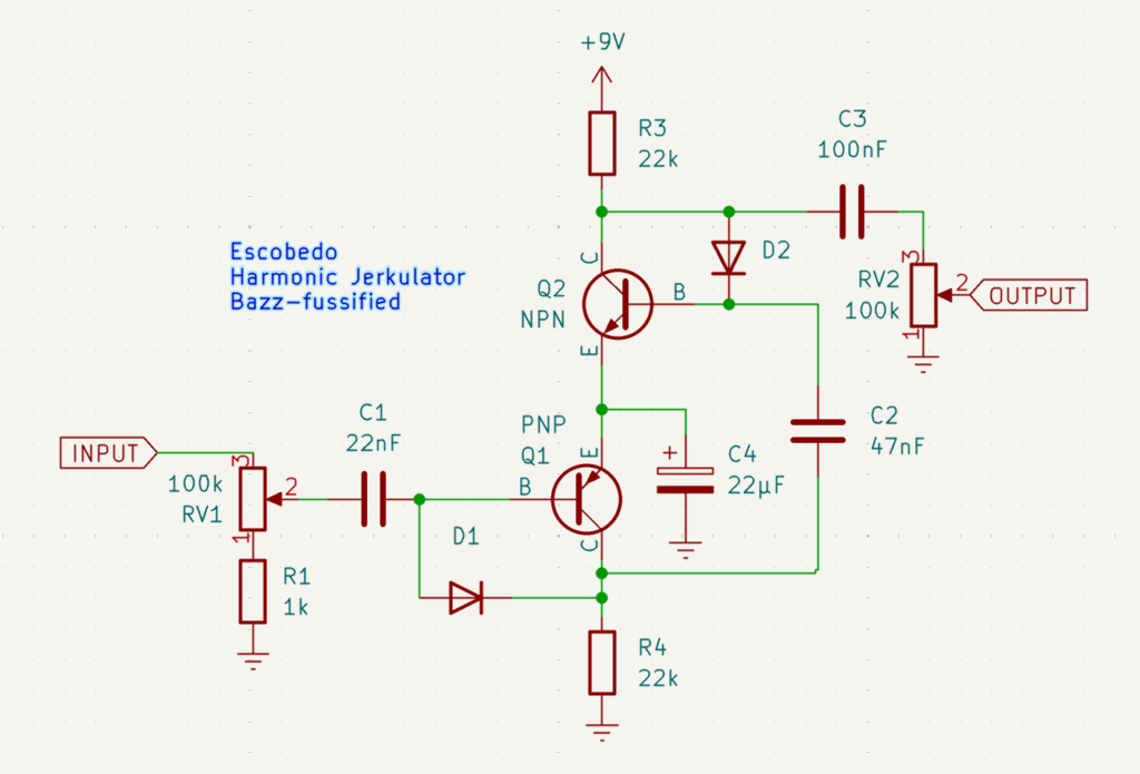
Note the orientation of D1; rather than pointing from the collector to the base, the diode goes from base to collector. Since the base is going to be more positive than the collector, you need to make sure the diode’s cathode is pointing towards the more negative side. This comes into play whenever you bazz-fussify a circuit involving a PNP (see the Bazz-Me-Fuss-You below).
As with the Bazzrite Fussrite, you’ll likely find that the output of this circuit is rather raspy and noisy. A small miller capacitor, perhaps 10-100pf, in parallel with the diode on the first stage (the PNP transistor), will help tame a lot of the noise. And of course, experimenting with the values of R3 and R4 can help to make a smoother cleanup if desired.
4. Some example schematics of Bazz-fuss-based fuzzes
The above ideas for bazz-fussifying circuits are really more starting points than finished circuits; they work, but lack a bit of the refinement of a fully fleshed-out circuit. In this section, I’ll talk through a few examples of circuits I’ve actually built and completed based on these ideas.
4.1. The Brazz Flush
The Brazz Flush was an attempt to try out many of the simple modifications to the basic bazz fuss that I detailed earlier. The circuit looks like this:
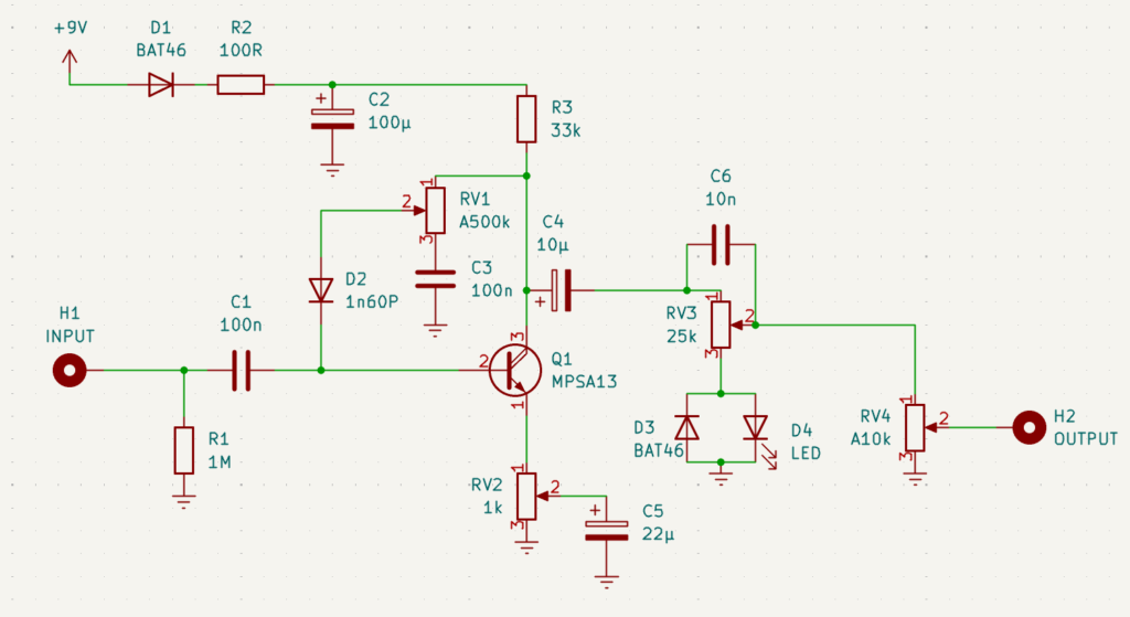
Some of the modifications to the basic vanilla circuit include:
- D1, R2, and C2 are a pretty standard addition for using a 9V adapter. They provide polarity protection and filtering of power. A larger value for C2 might be in order if you have a particularly noisy power source. R1 is a pull-down resistor to prevent popping when toggling the effect. These are fairly boiler-plate additions in any real circuit.
- RV1 implements the headroom or “leak” control. C3 is possibly of dubious value, but provides some filtering at the lowest headroom setting that smooths the highs. Builders might want to experiment with leaving it out (and leaving lug 3 of the pot unconnected).
- RV2 implements a gain control. A higher value might be needed if the circuit doesn’t clean up at minimum.
- RV3, along with D3 and D4, implements a saturation control. Any combination of diodes may be used, but here I’ve chosen a Schottkey in combination with an LED for a very asymmetric clipping, which can be adjusted by the potentiometer. C6 provides a thinner, brighter sound when saturation is at max.
- Note that D2, the biasing diode, is a Schottkey (1n60p). Since we’re implementing a headroom control, this provides maximum fuzzing at the lowest headroom setting. Remember that R3 might require some precise adjustment due to the finicky nature of Schottkey bazz fusses.
The result of these changes is a circuit that is quite versatile, able to go from intense fuzz to a pleasant overdrive. Of course a tone control might round out the feature set nicely.
You can listen here to an audio demo:
4.2. Lobo, King of Currumpaw
We’ve already discussed the basic idea of the Bazzrite Fussrite, but here’s an actual example of a circuit which I actually put in a pedal. This is a circuit I created for a Scout charity auction which I dubbed “Lobo, King of Currumpaw”:
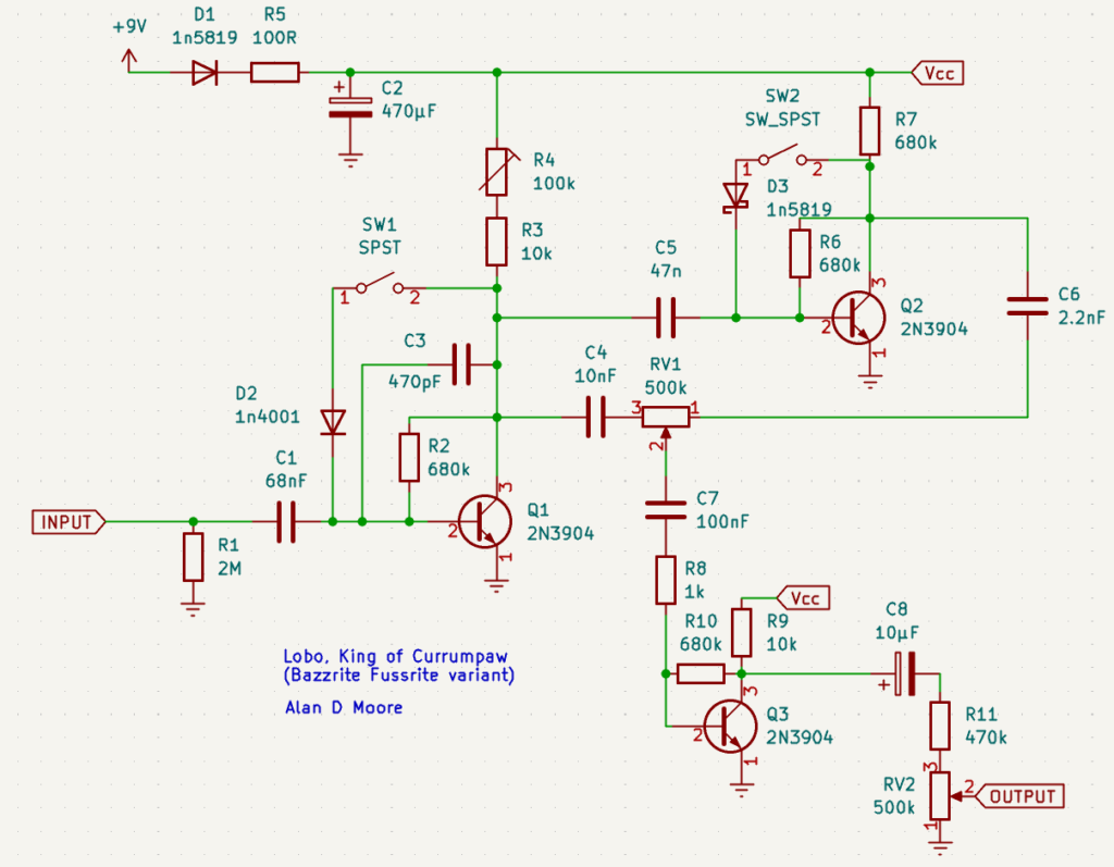
A number of significant changes have been made to the vanilla Bazzrite Fussrite circuit:
- Of course we have the boilerplate additions of polarity protection, power filtering, and anti-pop resistor. R1’s value was probably selected on the basis of component availability, anything 1M or higher is probably fine here.
- Stage 1 of the circuit has been tuned to be smooth and bassy. The coupling caps C1 and C4 have been increased to allow more bass and C3 has been introduced to tame the highs. Trimpot R4 allows for fine-tuning of the bias for a smooth cleanup. Biasing diode D2 is a standard silicon, providing a moderately loud output.
- Stage 2 of the circuit has been configured for a brighter, edgier output with gated cutoff. Schottkey diode D3 provides a high degree of compression and fuzz, and R7 is chosen to purposely mis-bias the circuit. Coupling cap C6 cuts significant lows from the output.
- The Blend pot RV1 thus pans between a very bassy, smooth sound from stage 1 and a raspy, sizzly gated sound from stage 2.
- Note that each stage has a toggle that removes the diode, leaving the
680kresistor to bias the circuit. Toggling both diodes off results in something more akin to the original Mosrite circuit – a rowdier, less-compressed sound. Different combinations of the toggles and the blend control provide a wide range of possible fuzz tones. - The final boost stage, implemented by Q3 and its adjacent components, is added to compensate for possible lower-than-unity output. This can happen both because of the Schottkey diode in stage 2, and also due to cancellation at middle-points of the blend knob. The latter is just an inherent problem with the Fuzzrite topology: since each stage inverts the signal, the output of stage 2 will always be 180 degrees out-of-phase from the output of stage 1.
The final fuzz circuit offered a wide range of high-gain fuzz tones, though clean-up wasn’t so great. Some of the more intense settings allowed for artifacts like sub-octave generation. Definitely a savage wolf of a fuzz!
Listen to the audio demo:
4.3. Bazz Me, Fuss You
This is one of my favorite bazz-fussified circuits, the “Bazz-Me-Fuss-You”. This circuit is based on Tim Escobedo’s Push-me-Pull-you, a 3-transistor octave fuzz, shown here:
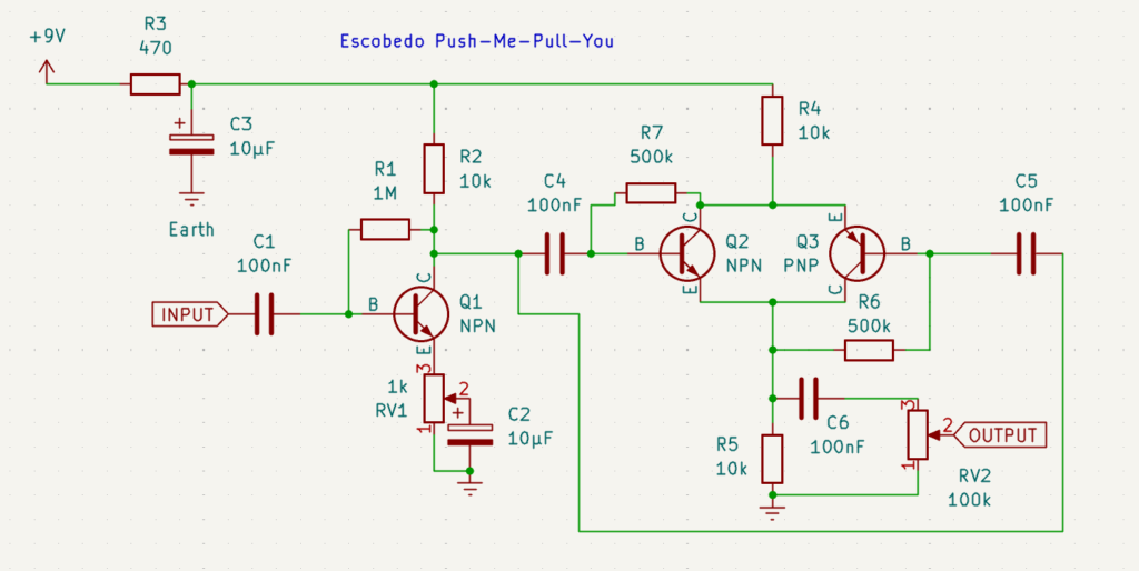
The first stage of this circuit, centered around Q1, is simply a boost that brings the signal up to a level that it can adequately drive the second stage.
The second stage is a little more complicated. We have an NPN and a PNP transistor with each one’s collector connected to the other’s emitter. As the input signal goes positive, the NPN will begin to conduct current, while the PNP will begin to close off. When the signal swings back negative, the reverse happens. In theory one would expect the actions to cancel out, but they do so imperfectly. Thus lower frequency signals (like the fundamental of the wave shape) are canceled, but upper frequencies are not. This gives a bright octave effect on the output.
To initially bazz-fussify this circuit, one simply replaces the three biasing resistors – R1, R6, and R7 – with diodes. As one might expect, this will then require a bit of refinement if you want something that isn’t an unholy mess. I’ve put this circuit idea through a few iterations, but here is the current one as of this writing:
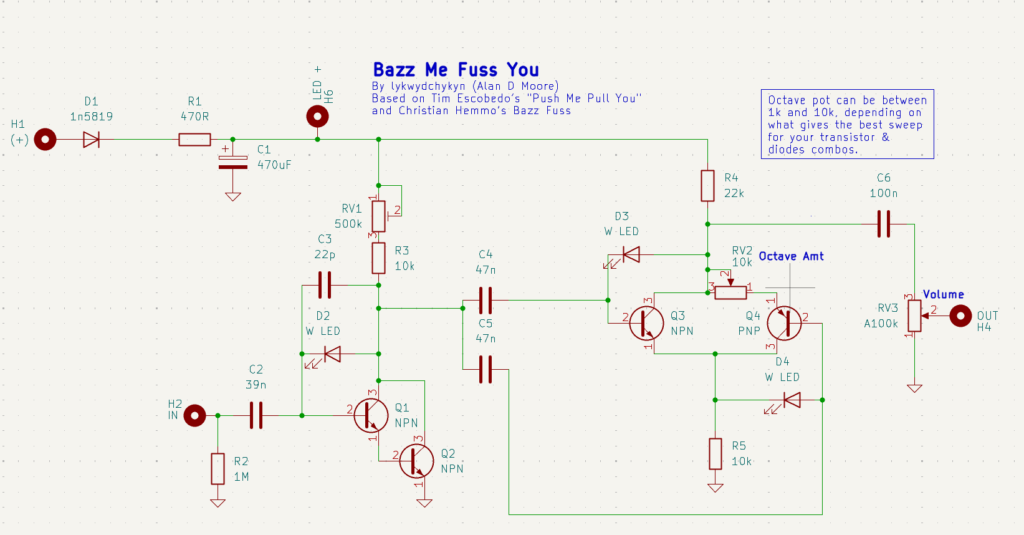
Let’s go through the main points of converting one circuit into another, starting with the initial boost stage:
- The stage one transistor has been replaced by two transistors in a Darlington pair. This makes it easier to dial in a smooth cleanup for the first stage.
- The 1M feedback resistor has been replaced by a diode, of course; in this case, a white LED.
- The gain control was removed, as anything less than full gain was deemed less-than-pleasant sounding. It could be added back if desired.
- A trimpot was added to the collector resistance to allow fine-tuning of the stage’s bias.
- Finally, a 22pF capacitor was added in parallel with the diode to tame the high end and eliminate RFI noise.
Now for the octave stage, the changes go like this:
- The 500k bias resistors are replaced with White LEDs. Note the orientation of the diode on the PNP transistor. As with the harmonic fussulator, it must go from base to collector due to the reversed polarity.
- A 1-10k “Octave” pot is inserted at the emitter of the PNP transistor. Initially I implemented octave as a 1M at the base of the PNP, but this change was stumbled upon by another builder and seems to work better. Putting a pot or switch at the emitter is apparently a very old modification for the Push-me-pull-you, and was employed in the JHS Lizard Queen.
- The output is moved to the collector of the NPN transistor, as this provides a good deal more volume, but the same basic tone.
However we configure the octave pot, it essentially removes the PNP signal from the output, leaving us with something like a two-stage bazz fuss in its place. The result is a fuzz that can go from full and raucous to clangy and raspy with a pronounced upper octave. Quite a nice sound if you like the octave fuzz thing.
Listen to an audio demo:
5. Conclusion
Although it’s been over half a century since the first fuzz circuits were unleashed on the guitar playing world, it seems we still have no end of ideas for thrashing a guitar signal into utter beautiful chaos. Whether you are a novice piecing together your first fuzz circuit or an experienced builder searching for new ideas, I hope this article has inspired you not just to explore the bazz fuss as a means to this end, but also to invent a few new ones of your own. Even if you aren’t a particular fan of the fuss, perhaps the meta-process of exploring a simple circuit idea and applying it in different ways to other circuits has inspired you to begin understanding the circuits you appreciate on a more conceptual level so that you can expand on them and apply them in new and interesting ways.
Thanks for reading, and happy building!


I am just starting out with pedal building and electronics in general. I’ve been not only trying to figure out how to build a bazz fuss, but also understand how it works. This was well written and very helpful, thank you.
Hi
I drew so much inspiration from this article. So I figure it might be in order to give back a little trick I cooked up.
I am building a Bazz Fuss as an onboard fuzz for my bass. It was important to me that all pots work at about unity volume. So for a gain/dist-control I came up with this:
* Take a stereo pot and replace the lower of the two resistor paths (<- English is not my native tongue. I hope it is clear what I mean) so you end up with a 500k lin/1M lin stereo pot.
* Wire the 1M part as "headroom control"
* Wire the 500k part as a volume pot in front (!) of the Bazz Fuss
So by turning one knob you get the cleanup from both those pots but their respective volume changes cancel each other out very nicely. You go from "full fuzz mayhem", to distortion, to overdrive and to "hairy, non-linear but pretty clean" sound without having to adjust the volume. Me gusta.
Some construction notes:
* The pre-volume doesn't go to ground directly but through a resistor. That way it is never completely off. I selected a value of 30k or so for optimal unity gain between fully clockwise and fully counterclockwise.
* You might want to select a lower gain transistor or it will still clip harshly (and pretty unpleasantly) on big spikes in the minimum-gain setting.
* The overdrive and cleanish setting sounded too muffled for me. So I put a treble bleed capacitor between the input and the output of the pre-volume pot. That part is currently not on my breadboard but I think it was about 100pF or less (select to taste). That way you actually get a pretty hefty (but dirty and pleasant) treble boost.
* Replacing the lower resistor path of a 16mm stereo pot is pretty easy. Bend the four bottom shackles/flaps (<- again I hope it is clear what I mean), lift off the resistor path, replace it with one you similary sourced from another pot and bend the shackles back in place.
That whole project lost a little momentum in the last months (The body cavity is routed. So it IS going to happen) but I know a guy who already uses it "in the field" and is very happy with it. So consider this tried and tested 😉